Pile Cap Theory
The program produces the following design output:
Required pile quantity and layout to satisfy loading applied to the footing and self weight of pile, based on bearing, uplift and lateral pile capacity. Moments are also being considered for lateral loads applied at top of pile cap. Moment arm used in case of lateral loads is (Pedestal height + Pile cap thickness). Pile reactions are calculated based on Bolt Theory.
Geometry of the pile cap based on shear and bending strength requirements at critical sections of the footing.
-
The user provides the following pile properties: capacity (bearing, uplift, and lateral), diameter, spacing, and edge distance. Based on these parameters, the program determines the required pile configuration as well as plan dimensions of the footing from the condition, that the force, along with the self weight of pilecap, transferred to any pile should not exceed its capacity. For a general case of vertical and horizontal forces, and bending moments acting on the cap, that stipulation is equivalent to satisfying the following two equations:
Hpile ≥ Happl / N
Hpile = Single pile horizontal capacity
Vpile = Single pile vertical capacity
Happl = Total horizontal load applied
Vappl = Total vertical load applied
N = Total number of piles in footing
Mx,appl = Applied bending moment about X-axis
My,appl = Applied bending moment about Y-axis
Rx = Distance from Y-axis to the farthest pile
Ry = Distance from X-axis to the farthest pile
Note: X and Y-axes above are centroidal axes of the pile group, Ixg and Iyg are calculated treating each pile as a unit, and are equal Σ(1*yi2) and Σ(1*xi2), respectively.The program includes a library of possible pile layouts for quantities from 2 to 25 piles. Based on the user input, the program recommends the most economical (least number of piles) layout. The user may select any other layout/quantity if desired, however. In addition, changing the coordinates of individual piles may modify the selected pile layout. Alternatively, the user may input the entire configuration by hand.
The layout recommended by the program is guaranteed to satisfy the load/capacity ratio for all piles. Should the user-modified or manually input layouts result in pile overstressing, the program will flag this deficiency in the design output.
-
Proportioning of the pile cap involves satisfying the shear (one and two way) and bending requirements at applicable critical sections, in accordance with Chapter 15 of ACI 318-02 (for US job).
One way shear is checked in two areas:
- At outer piles, with the critical section located at a min. distance d from the face of a corner pile or faces of a pile group along the edge of the footing,
- At the distance d from two orthogonal faces of the pedestal.
The critical shear plane is assumed along a shortest straight line connecting free edges of the footing. The design is then performed for the total pile reaction force on one side of the shear plane, in accordance with Sections 11.1 through 11.5.
Two way shear is checked in three areas:
- At outer piles, with the critical section located at a min. distance d/2 from the face of a corner pile or faces of a pile group along the edge of the footing. The critical plane is assumed to be positioned along a straight and curved line, so that the total section length is minimized.
- At the distance d/2 around the pedestal. The section comprises four straight-line segments, parallel to corresponding sides of the column.
- At the distance d/2 around a pile.
The design is performed for the total pile reaction force acting within the perimeter of the critical section, in accordance with ACI 318 Sections 11.12.2 through 11.12.6 (for US job).
Development length is checked for straight rebar. If development criterion is not met by the footing geometry a warning message is displayed in the calculation sheet, user can go for other detailing options like bent bars.
Flexure is checked for critical planes located at both faces of the pedestal. The bending moment is calculated as an aggregate of moments due to pile reactions on one side of the plane.
Determination of an individual pile contribution to the forces at a critical section is based on whether the pile is outside this section (full reaction value assumed), inside the section (reaction ignored), or at an intermediate location (partial reaction assumed), as per Section 15.5.4(for US job).
Pilecap design through IS Code
-
Design method in IS code is not similar with other combinations. The design philosophy followed in STAAD Foundation Advanced is explained below-
Pile cap module is following rigid method.
Pile Reaction calculation is done using Bolt Theory. For combinations other than 2/3 pile, Moment is calculated at column face in both direction (Considering each pile reaction and pile location. If any pile area is intersected by section line taken for moment calculation, partial reaction of the respective pile is considered). Same thing is done for shear but at a dist of d-effective from column face.
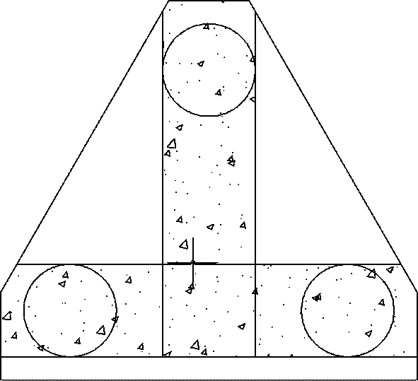
For three piles, although pile reactions calculation are done using bolt theory but shear force & bending moment calculations are slightly different for IS code. Instead of considering whole triangular slab, two beams are considered; one beam extends from one pile to another pile and another beam extends from third pile to center of first beam. In plan these beams make T shape. These beams are named as BASE BEAM & ALTERNATE BEAM.
-
Designed only for axial load and Moment along longitudinal direction; program does not consider transverse moment in design. Two Pile reactions are calculated from Rivet theory, pilecap design is done as a beam (shear force and bending moment along longitudinal direction)
Design output displays applicable code sections used for foundation design for all codes.